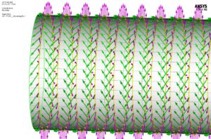
Example of pipe body composite ply orientation
The advanced engineering team at Magma continuously refines the design of m-pipe laminate layers to optimise strength and minimise weight, whilst ensuring the PEEK and carbon fibre thermoplastic composite pipe is cost-effective to manufacture. Reducing the amount of material reduces the consumption of the fossil fuels. The lightweight nature of m-pipe means minimises costs as smaller installation vessels are required and installation is simple. Meanwhile its flexibility removes the need for complex metrology and bespoke steel manufacture.
Prior to investing in advanced simulation software, Magma’s design process was like most in the industry. Designs for a particular application needed to be physically tested, which very quickly drives up costs and lead times.
Simulating service life conditions for TCP
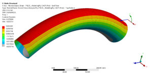
Advanced simulation software from ANSYS has drastically altered this process through realistic simulations, where actual test behaviour is replicated in the structural response of a numerical model for service life load combinations. We can produce a qualified product, exceeding customer requirements, throughout the design cycle, all the way through to end of life in an incredibly fast timeframe.
Numerical simulation with ANSYS Workbench FEA (Finite Element Analysis) changed the process allowing our Computer Aided Engineering (CAE) team to rapidly consider different options through efficient scripts within Workbench. Numerous iterations can be assessed to validate the structural integrity of m-pipe. The number of physical tests has been dramatically reduced and they now have become confirmatory. Each test is also strain gauged to allow correlation against the numerical model.
The ability to simulate m-pipe service life conditions is good for clients. We not only share structural analysis results, including stress and strain plots, but we also interface with DNVGL to gain class approval. As a result, we can produce some of the most robust thermoplastic composite pipe in the oil and gas sector, which can cope with extreme operating envelopes, with the least possible material required. This helps to keep product costs as low as possible.
Magma’s CAE Process Although the concept of a composite pipe appears relatively simple, in practice the numerical models are extremely complex. The laminate can comprise over 50 layers with each layer orientated to optimise structural performance while remaining within manufacturing
parameters. A metallic end-fitting is secured at either end to provide a robust connection to third-party equipment. The analysis sequence simulates the service life of the product which covers storage, transportation, test, installation and operation.
The first step is usually an investigation using Orcaflex to determine the system global response. This is used to extract the local forces and moments for application to the pipe body and end fitting FEA models. Orcaflex is also used to simulate transpooling operations of the pipe around the Magma site as it comes off the manufacturing reels on to storage reels or for lifting operations.
Pipe Body FEA
We have developed our own pipe body ‘Magma ANSYS Pre and Post Processor’ (MAPPS) interface which provides an easy to use design tool for all Magma engineers without the need for in-depth knowledge of ANSYS. Input data produces a three-dimensional FEA model using a twenty-node layered element with quadratic behaviour, which is required for modelling thick composites. MAPPS also allows the input of individual ply properties and the retrieval of stress and strain results.

Key aspects of any composite model are the ply material properties. We have completed extensive physical testing to derive this information. Each solution takes seconds to complete allowing the laminate construction to be quickly optimised using our graphical interface.
The pipe body is designed in accordance with DNVGL-ST-F119 and DNVGL-ST-C501. As m-pipe is composed of numerous lamina at differing angles and potential different material characteristics, they must be assessed individually to ensure the various failure criteria are not exceeded. We use the maximum strain failure criteria to carefully assess the fibres and matrix within each ply both along the length of the pipe and through the laminate thickness.
In addition, component results are also orientated into the system to determine axial, hoop and radial values.

End-Fitting FEA
The end-fitting assemblies are fabricated from super duplex stainless steel. It comprises an arrangement of concentric components that generate a radially compressive pressure sandwiching the pipe body without the need for any bolt or pinned connections which would compromise the laminate integrity.
The structural analysis is performed using an FEA assembly model created based on CAD geometry provided by the design team. Minor features, such as threads, non-critical holes and small blend radii are then easily removed.
To allow the application of external loads a section of the pipe body is included in the end fitting FEA model. Classical laminate theory is used to calculate the equivalent orthogonal stiffness values for the pipe to simulate the composite behaviour without defining the laminate. Sensitivity studies ensure the element density is adequate in the critical areas e.g. stress concentrations.
The end-fitting is designed in accordance with Section F100 of DNV-OS-F101 which requires mechanical connectors to be designed against ASME VIII Division 2. To verify the design of the end fitting the following design checks are performed:
• Protection against Plastic Collapse
• Protection against Local Failure
• Protection against Hydrogen Induced Stress Cracking (HISC) in accordance with DNVGL-RP-F112
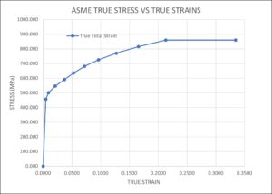
To accurately simulate the load path through the end-fitting assembly contact between individual components including the effect of friction is included. Stress-strain curves are defined for the super duplex material including the effect of temperature. This, in combination with the contact, means the analyses include the effect of both non-linear material and geometry.

To represent each service condition a sequential loading combination is applied to the FE model as a series of non-linear steps. This can mean up to 10 load steps are applied including thermal expansion, pressure, axial tension and bending moment
Detailed ASME integrity checks are undertaken to ensure the combination of end fitting and m-pipe body are fit for purpose in accordance with an internationally recognized pressure vessel and sub-sea design code.
Presenting virtual results helps oil operators understand the behaviour of m-pipe. Our analysis provides clear and concise information that can easily be interpreted by all parties. The outcome is less risk, greater customer involvement and confidence up front.
As part of our ISO 9001 quality assurance system a thorough independent check is undertaken on each new FEA model to ensure the assumptions are correct and the subsequent results are acceptable. A technical report is also submitted to the client or DNVGL for review.
Future developments
Our investment in digital engineering has enabled the most cost effective yet high performance pipe to be proven at minimal engineering cost. We plan to extend the Magma standard ANSYS material library, further refine integrity checks, automate results post-processing and improve contact behaviour to reduce solution times further. Our engineering tools dramatically reduce testing time and expedite projects efficiently and accurately.
Written by Steve Bell for Oil and Gas Innovation